Author: Ryan Jørgensen

German Semaphore Train Signal LEGO® Model

Modelling a German semaphore train signal, and operate it “by wire”

A railroad need signals, and adding signals to a LEGO® railroad layout bring a sense of realism to the operation. Since I currently live in Germany, and previously been modelling with the German railroad history as model, the signals will be German style.

We were on a small weekend-escape south of Hamburg this September, and we were staying just next to the regional “Heidebahn” railroad between Buchholz and Hannover, close to the station of Handeloh. There, I came across these – in my mind – beautiful operational semaphore signals.

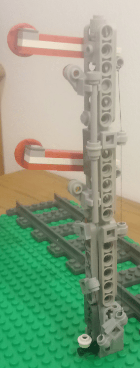
The left signal is the Main Signal (Hp “Hauptsignal”) , capable of showing drive, slow and stop. The right signal, with the orange/white circle is a Distant Signal (Vr “Vorsignal”), showing what to be expected from the signal further down the line. Read more about the different states/aspects of the German signalling system on Wikipedia

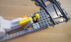
I found two main challenges. The first was to make the footprint of the arms as small as possible, while still keeping the red-white-red line true to model and keeping the arms free to move. For this, I did a ‘hack’, using a 3L bar for pivoting, and leaving a hole of one plate high + half stud wide in the arm. In this way, it was possible to keep the arm footprint 1 stud wide and 1 brick high. My first idea was to use a 1×1 Technic brick w/hole for fastening the arm to the mast, but that would require at least 1 brick + 1 plate high – and it didn’t look good.

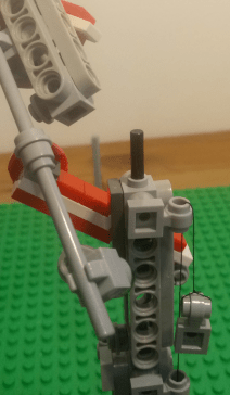
The other challenge was the mast itself. I would like to make it as slim as possible, while still showing the lattice structure. I used thin 1×6 technic liftarms to mimic the lattice, and put them on 1×1 modified brick, stud on all 4 sides, securing them with some bars trough the open studs.

At the end of both arms towards the mast, “wires” are attached, which then run down on the side of the mast, and can be used for operation the arms.

I am not completely satisfied with the look, and I have some ideas of reducing the footprint, while keeping the lattice impression, using a 180 degree SNOT (read about SNOT here)

Another good looking option would be using the out-of-prduction and rather expensive train signal support lattice, or the newer (slightly cheaper) support lattice mast. The 1 x 4 x 1 fence might also be usable.

The final result can be seen below. Another post in near future will be about motorizing the Semaphore signals!

Automatic LEGO® train decoupling solutions

Post reviewing the different types of automatic decoupling solutions

In order to have an automatic, “no-touch” railroad layout, an automatic decoupler is high on my wish list. I visualize a shunting yard with a ladder, where I can rearrange the consist of freight trains, and have a somewhat prototypical operation.

There are in short 4 types of decouplers that I am aware of:

1 – Decoupler under/between the rails

A beam stretches upwards and catches the undercarriage of the wagon. These solutions rely on the inertia/speed or at least the wheel grip of the locomotive, to overcome the pulling force of the magnets.

  • Pro: The solution can be made very small and compact
  • Con: It will always decouple by the weakest magnet link – so it is mainly useful four decoupling a single wagon or a complete set of i.e. passenger cars.

The solutions can be:

  • Passive: Always decouple when running the train forward over the decoupler. No motorization required!
  • Active: The beam can be raised/lowered, allowing for running on the track in both directions, and actively manage the decoupling.

Examples:

2 – Sidebeams + pushing wagons/magnets from each other

This solution drives a beam in between the wagons you want to decouple, and actively pushes them away from each other, to overcome the magnetic pulling force.

  • Pro: You can decouple anywhere in a trains consist, making it very flexible and more prototypical.
  • Con: Depending on the motors, the build can take up quite some space. The stopping location of the train must be very precise.

As in the first video in examples below, it might be possible to use only one motor to separate the magnets. The video features trains with the old style open magnetic couplers. I will try to check whether it also works with the new style magnets, or if I have to stick with a design, where I am actively pushing the wagons apart. More about that in upcoming post.

Examples:

3 – Blocking wheels of wagons / 4Dbrix

Another way of decoupling is to “lock” the wheels of the wagon, and drive the locomotive away, thereby decoupling. Intuitively, this would give the same problems as with solution 1: The wagons will decouple at the weakest link in the consist. The 3rd party manufacturer, 4Dbrix, however claims that this is not the case.

  • Pro: The smallest footprint on the reviewed solutions.
  • Con: May decouple only at the weakest link of the consist. It is NOT easily operable with Mindstorms, but instead operated by the free nControl PC software by 4Dbrix.

Link to product: https://www.4dbrix.com/products/train/2-04-017-decoupler/

4 – Original LEGO® 12v decoupler

LEGO® made a decoupler for the 12v train era back in the 1980s. It is difficult to get your hands on, and from what I can see from forums etc., it is not 100% reliable.

An idea for the future could be to build a similar solution, where the twisting mechanism is raised up between the tracks.

See a review here https://www.youtube.com/watch?v=EAeQRgs6qCU

Automatic LEGO® Container Yard – Post 2: Lifting and moving

Prototype on lifting and moving containers in a container yard

After building the container grabbing mechanism, time has come to move the container around:

The video is shown in double speed.

The lifting mechanism is designed using rack and pinion gears, distributed in four corners, to increase stability. The grabbing mechanism has the rack mounted, and the pinions are mounted on the overhead crane, enclosing the grabbing mechanism, to make it more stable.

Rack enclosed by gears/pinions in four corners. The crossbeams on top of racks are forcing the racks towards the gears.

The reason for having the pinions on the overhead crane, and not on the grabbing mechanism, is simply to make the grabbing mechanism lighter by not having another motor mounted on it.

Another design consideration is to have the same number of gear interfaces from the motor to both sides of the pinion/racks. At my first iteration, the motor was driving one side of the pinions directly, while the motion was directed to the pinions on the other side by gears and shafts. However, since there is some slack in the gears, it introduced a delay in the reaction of pinions on the other side, and the grabbing mechanism was lifted unevenly and wobbly. In the final prototype the motion is first directed to the center, and then directed to the two sides. There is still a slack and delay, but is evenly across the two sides.

Details of the centered motion distribution from motor to gears/pinions

The overhead crane has the weight of the motors evenly split on the two sides, moving as much weight as possible away from the center and reducing the need for reinforcement of the crossbeams.

Simple movement of the overhead crane

The movement in X-direction/crosswise is very simple. A motor, gear and racks in one side, and wheels on the other side, running on a smooth surface. The wheel side has a slight delay in reaction, as it is being “dragged” by the gear/rack side.

To solve this, there would have to be gear/rack on both sides, and the equivalent number (and ratio) of gears between the motor and racks on both sides – same principle as with the grabbing mechanism described above. For now, I decided that the lag on the wheel side is manageable, but I might correct it later, if the crane turns out to be too imprecise.

I experimented with several truss designs for the beams on which the overhead crane is resting on, but I ended up with using the 5×7 liftarms w/ open center, supported by a few other liftarms. This is lighter, but still sturdy.

The next steps will be to create the basis for moving the overhead crane in the X-direction/lengthwise, and introduce some kind of optical recognition/barcode for the containers, so the system can store the information on which containers are stored where.

Automatic LEGO® Container Yard – Post 1: Grabbing the container

First thoughts on an automatic container yard, and a container grab mechanism

As a part of my train layout, I have been thinking about a fully automated container yard – of course controlled by the LEGO® EV3 Mindstorm. My idea: A train comes in, the gantry lifts the container of the wagon, identifies the container, and place it on an empty spot in the container yard.

It sound simple – but it’s really not. The challenges are:

  • XYZ: The gantry must be able to move parallel and perpendicular to the track (X & Y) to move to the right location, and up/down (Z), to place/pickup container from the yard or a wagon.
  • Precise: The mechanism needs to be very precise, else there will be a need for adding many sensors for aligning etc. With millimeter precision, it has to place the container at an exact location, stored this location in a database, and be able to return to that location for picking up – only relying on the XYZ coordinates of the container location.
  • Identifying containers: My initial idea is to identify containers using a color-“barcode”. More about this in another post.
  • Grabbing container: The gantry needs a mechanism to grab a container, with 100% reliability, and without allowing the container to rotate. If the container rotates, it will be nearly impossible to operate without adding active aligning.

I started out by investigating on the grab mechanism. First attempt was to use the linear actuator, and pivoting fingers, like in the LEGO® set 42006. However, this design was a bit too wobbly, and the grab mechanism tended to rotate a bit, due to the axle rotation into the actuator.

The “test container” has a 1×1 Studded Technic Brick in each corner, where the grab mechanism can lock in:

Instead of using the actuator, I tried to go for a design, where hooks in each corner pivots very closely to the container. Additionally, I added some passive guides, to align the grab mechanism into place.

I am very happy with the result! It is much sturdier and very reliable! (I haven’t tested it a 100 times yet though…). See the the video below.

Motorized LEGO® train switch with Mindstorms

An example of motorizing a LEGO® train switch (turnout), and controlling it from Mindstorms

A goal of mine is to – someday – create a more or less automated running LEGO® railroad layout. One of the steps towards that is to operate the switches by motors, and then control the motors by programming on the EV3.

Inspired by a video (which I can’t find again and credit properly), I simplified, and made the shown design.

Two 16 long studded technic bricks keeps the motor in place, and is attached to the switch with normal bricks. This can be done in many ways, and probably also more compact and sturdier than this design.

A 5 long liftarm is attached to the motor, and 2 x thin 4 long liftarms are connecting to the switch. The thin liftarms has an axle hole at the ends, which can hold the tap of the lever.

This was the easy part. The programming is also not difficult – it is basically just turning a motor a certain number of degrees. The tuning of the degrees needed as well as the speed takes some time, but I found an angle of 43 and speed of 50 works well. See my code at the end of this post.

Functional motorized LEGO® train switch, operated by Mindstorms EV3.

Videos of other builds using Mindstorms to control the switches:

My code example used in the video:

#!/usr/bin/env python3
from ev3dev.ev3 import *
from time import *

# Connect motors and sensors
ts = TouchSensor("in1")
lm = LargeMotor("outA")

# Variables for tuning the switch.
# Make sure that the polarity of the motor is right.
# Test it before attaching the motor to the switch.
degrees = -43
speed = 50

# Make sure that the switch is manually put to "straight" position
# before running the program. Below resets the angle counter
# of the motor to zero.
lm.position = 0

def main():
    # direction of the switch: 0 = straight, 1 = turn/diverting
    switch_state = 0
    while True: # Loop forever - press back button on EV3 to stop.
        if ts.value() >= 1:   # If touchsensor pressed.
            if switch_state == 0:
                lm.run_to_abs_pos(position_sp=degrees, speed_sp=speed, stop_action="brake")
                Sound.speak("Turn")
                sleep(3)
                switch_state = 1
            elif switch_state == 1:
                lm.run_to_abs_pos(position_sp=0, speed_sp=speed, stop_action="brake")
                Sound.speak("Straight")
                sleep(3)
                switch_state = 0

if __name__ == '__main__':
    main()

More sensors – Mindsensors.com Sensor Multiplexer

The EV3 has 4 sensor ports. To increase number of ports, a sensor multiplexer might be the answer. This post explains the use of Mindsensors.com EV3SensorMux

EV3SensorMUX-front-resized

As soon as you want to create more sophisticated, multi-functional robots, you run into the sensor limit. The sensors are what makes your robot aware of the world surrounding it, and the more the robot can sense, the more precise it can act.

The Mindsensors.com EV3SensorMUX provides the possibility to connect up to 3 sensors to 1 sensor port. The result is an increase to a total of 6 sensors ports (from 4 + additional 3, less the one used for the EV3SensorMUX.

There are four pin holes, compatible with the standard LEGO® connection pins, for attachment. 5 studs wide and 6 studs longs.

The EV3SensorMUX only supports original LEGO® EV3 sensors – you won’t be able to use NXT or 3rd party sensors.

Using the EV3SensorMUX with EV3dev Python

If you are using the EV3-G visual programming environment from LEGO®, then there are designated, downloadable blocks available. However, if you want to use it with EV3dev Python, then there are a few more exercises to be done.

The code below first sets up 3 LegoPort objects, assigned the input ports of the EV3SensorMUX. The first in2 is the EV3 sensor port that the EV3SensorMUX is attached to – and the normal way to designate a EV3 sensor port. After the : the i2c communication protocol is specified, and the 80, 81 and 82 is are the ic2 port addresses on the EV3SensorMUX,  and the mux1, mux2, and mux3 are the actual ports, to which you can assign a sensor.The documentation on Mindsensors.com webpage, as well as the EV3dev docs, shows 50, 51 and 52 as the ic2 addresses, but for me it is not – or I simply didn’t understand it…

When plugging in the EV3SensorMUX you can find the full port addresses in the folder /sys/bus/lego/devices/ as in the screenshot. I am using MobaXterm for SSH terminal, as it has a good file browser). We can also see the driver for LEGO® EV3 color sensor is loaded by default. In the code (at the bottom of this post), we therefore have to set the right devices for each port.

Furthermore, the TouchSensor is an analog sensor, and we therefore have to set the mode of this port to analog. For the other ports, we don’t have to set the mode (only the sensor type), since the other sensors are the same type as the EV3 color sensor which was loaded by default. For an overview of the different sensor communication types, see here.

Also note, that because of latency (I believe due to file I/O), we will have to include a sleep command after each initialization, in order to have the right drivers etc. loaded. My experience is that if you are running the programs directly from a SSH terminal or on the EV3 itself, 500 ms is enough. Running the programs from Visual Studio Code requires 1000 ms (1 second).

Finally, using sound.speak to tell us when the sensor threshold value is reached/activated. Have a look at the result in this video:

mindsensors.com EV3SensorMUX in action…

You can also enjoy another implementation for a “Laser Harp” at this great site: https://ofalcao.pt/blog/series/lego-laser-harp

Code for example:

#!/usr/bin/env python3
# imports
from ev3dev.ev3 import *
from time import sleep, time
import sys

# -------------------------------
# CONNECTING SENSORS
# -------------------------------

# setting LegoPort interface
muxC1port = LegoPort("in2:i2c80:mux1")
muxC2port = LegoPort("in2:i2c81:mux2")    # (driver_name="ms-ev3-smux")
muxC3port = LegoPort("in2:i2c82:mux3")

# setting the 1st port on SensorMUX to analogue mode, to be used for touchsensor
muxC1port.mode = "analog"
sleep(1) # need to wait for analog mode to be set

# loading the devices for each port
muxC1port.set_device="lego-ev3-touch"
muxC2port.set_device="lego-ev3-us"
muxC3port.set_device="lego-ev3-ir"

ts = TouchSensor("in2:i2c80:mux1")
us = UltrasonicSensor("in2:i2c81:mux2")
ir = InfraredSensor("in2:i2c82:mux3")
sleep(1) # need to wait for sensors to be loaded. 0.5 seconds is not enough.

us.mode = "US-DIST-CM" # setting to measure distance in centimeters
ir.mode = "IR-PROX" # setting to measure proximity.

def debug_print(*args, **kwargs):
    # Print debug messages to stderr. This shows up in the output panel in VS Code.
    print(*args, **kwargs, file=sys.stderr)

def main():
    # writing initial sensor values
    debug_print("TS: " + str(ts.value()) + " IR: " + str(ir.value()) + " US: " + str(us.value()))
    while True:
        if ts.value() == 257: # 256 == not pressed, 257 == pressed
            Sound.speak("Touch sensor")
        if ir.value() <= 10:
            Sound.speak("Infrared sensor")
        if us.value() <= 50:
            Sound.speak("Ultrasonic sensor")

if __name__ == '__main__':
    main()

Lego® Camera Stand for Phone

Short post on an idea for building a “camera stand”, to avoid shaky photos from the phone.

If you, like me, have slightly shaky hands, taking a good photo from the phone – f.x. for this blog – can be a nightmare. So why not build a “Camera Stand” out of LEGO®?

Camera-stand-upright-resized Camera-Stand-landscape-resized
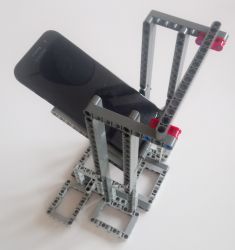
The pictured stand can handle both vertical and landscape photos, without the supporting structure obstructing the motive.

It is using a “cradle” of 3×5 L-shape liftarms, combined with longer liftarms for support. Vertical liftarms, on each side makes a “ladder” to which the cradle is attached using axles. This allows for putting the phone closer or further away from the motive.

For the inner part of the cradle, away from the motive, the axles are inserted into the cradle itself. For the outer part, towards the motive, the axles can either be inserted into the cradle, or the cradle can simply rest on the axles – the latter alows for better freedom in adjusting the angle of the phone, as you don’t have to match the holes of the ladder and the cradle.

Camera-Stand-nophone1-resized

The structure is a bit wobbly, and can definitely be improved, but it does the job, with the top horisontal liftarm attached for stability.

Intro

This blog and pages are all about Lego® trains, modelling and programming of the Lego® Mindstorms EV3.

I am by no means an expert, neither in programming nor modelling, but hopefully there are some tips/examples that others find useful. I have also tried to collect some of the many web resources that helped me exploring this hobby.

Have fun!

My journey (back) to LEGO®

I have been fascinated by trains since my little brother and I inherited a HO scale Märklin layout in our childhood. After abandoning the hobby for many years, I picked it up again back in 2008, but failed to create the big layout I was dreaming of, due to lack of space and time.

A few years ago, a friend of ours gave us a Lego train set as a present. That re-ignited my childhood fondness of Lego as well trains, and I was having a lot of fun building the 60052 Cargo Train set. Looking around for more Lego trains, I noticed the Lego Mindstorms EV3, and quickly decided to try it out.

It was amazingly fun to play with. Since then I have explored, build, programmed and planned a lot of fun stuff to do with Lego.